MySensors – Ogólny poradnik z przykładami.
Długo zastanawiałem się jaki wpis na blogu zrobić na temat MySensors. Ponieważ jest to oddzielna odnoga tak jak google home, node red itd. Zdecydowałem, że zrobię wszystko w jednym poście, bo ja w sumie będę potrzebował tylko dwóch efektów, ale przygotuje po to oddzielna kategorie i gdy nie będę miał co omawiać, lub wy będziecie mieli pytania, to będę uzupełniał, albo ten wpis, albo będę robił nowe wpisy.
MySensors dla mnie to połączenie arduino razem z raspberry pi. Programujemy MySensors w środowisku arduino, więc jeżeli ktoś już miał styczność z arduino to będzie mu na pewno prościej. MySensors to również środowisko dosyć specyficzne, ale dające dużo możliwości, bo nie ogranicza nas soft, bo w końcu go sami tworzymy. Korzystamy oczywiście z gotowych rozwiązań, ale możemy w kod wplatać własne wstawki.
Przejdźmy do podstaw, czyli musimy pobrać arduino:
– Link do pobrania arduino
Cały poradnik postaram się uprościć, więc będzie mocne spłycanie tematów, więć jeżeli Twoja wiedza jest ponad podstawę, to nic nowego nie dowiesz się z tego poradnika, ale jeżeli dopiero zaczynasz, to poradnik okaże się pomocny.
Arduino opiera się na „bilbliotekach”, czyli przykładowych kodach, ale w skład tego wchodzą również pliki, które są wysyłane do arduino bez konieczności ich edycji. W praktyce to bez tych plików nie zadziała nasz sketch.
#include <MySensors.h>
Powyżej widzimy przykład takiego pliku i nie mamy go w zakładkach, więc przepisanie całego kodu, ale nie posiadając tego pliku, nie pozwoli nam uruchomić prawidłowo sketch, żeby prawidłowo kod działał.
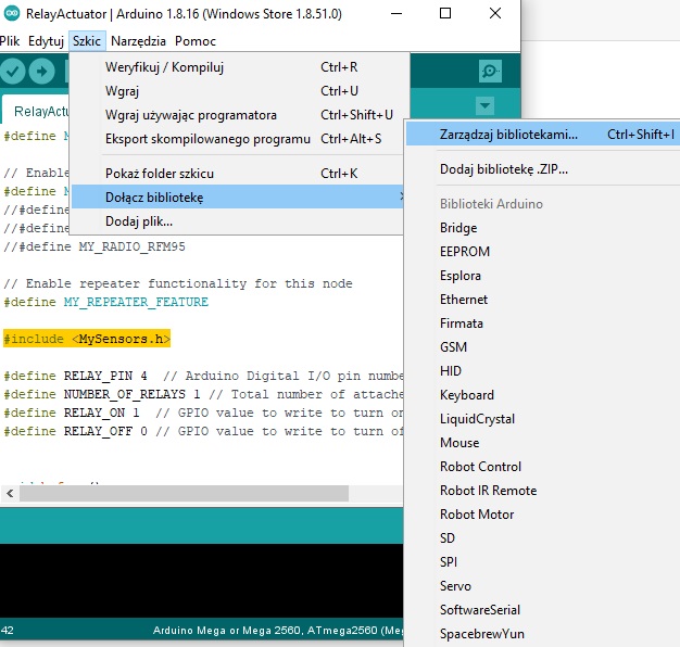
W Arduino otwieramy Szkic>>Dołącz bibliotekę>>Zarządzaj bibliotekami:
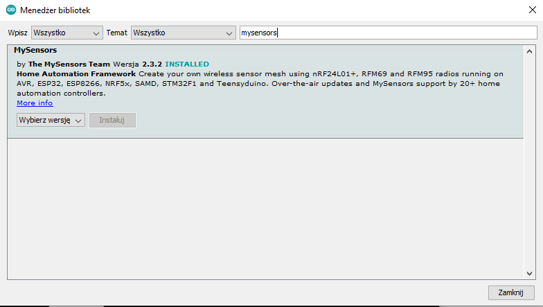
Wyszukujemy bibliotekę MySensors i instalujemy. Poniższe zdjęcie ma wyszarzony przycisk instaluj, bo tę bibliotekę mam już zainstalowaną.
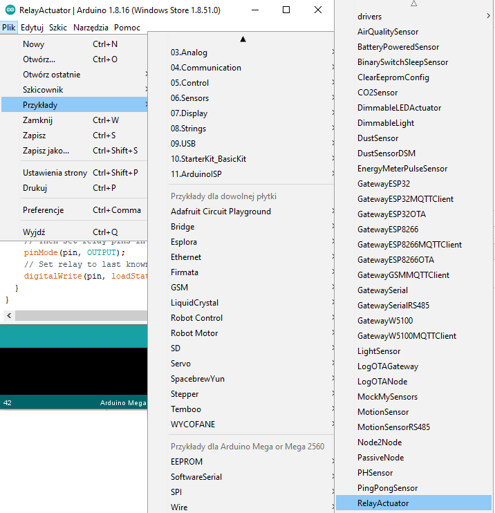
Po zainstalowaniu możemy od razu przejść do przykładów MySensors. W moim projekcie będę potrzebował sterowanie pinami w arduino mega i obsługą tego w domoticzu. Użyjemy do tego dwóch przykładów:
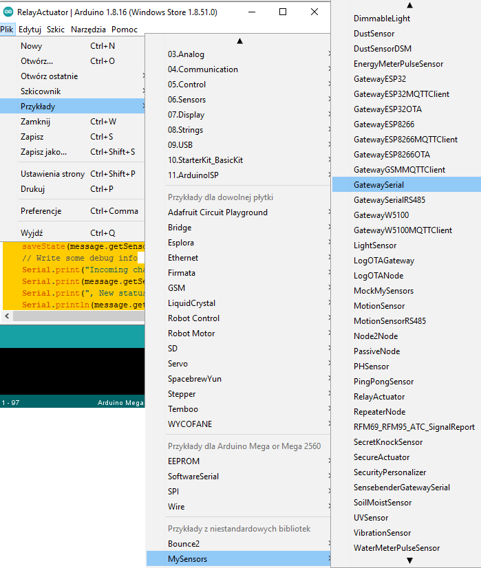
Wchodzimy Plik >> Przykłady >> MySensors >> RelayActuator
Dostajemy w Arduino kod, który będzie wymagał poprawek:
/* The MySensors Arduino library handles the wireless radio link and protocol
* between your home built sensors/actuators and HA controller of choice.
* The sensors forms a self healing radio network with optional repeaters. Each
* repeater and gateway builds a routing tables in EEPROM which keeps track of the
* network topology allowing messages to be routed to nodes.
*
* Created by Henrik Ekblad <henrik.ekblad@mysensors.org>
* Copyright (C) 2013-2019 Sensnology AB
* Full contributor list: https://github.com/mysensors/MySensors/graphs/contributors
*
* Documentation: http://www.mysensors.org
* Support Forum: http://forum.mysensors.org
*
* This program is free software; you can redistribute it and/or
* modify it under the terms of the GNU General Public License
* version 2 as published by the Free Software Foundation.
*
*******************************
*
* DESCRIPTION
* The ArduinoGateway prints data received from sensors on the serial link.
* The gateway accepts input on serial which will be sent out on radio network.
*
* The GW code is designed for Arduino Nano 328p / 16MHz
*
* Wire connections (OPTIONAL):
* - Inclusion button should be connected between digital pin 3 and GND
* - RX/TX/ERR leds need to be connected between +5V (anode) and digital pin 6/5/4 with resistor 270-330R in a series
*
* LEDs (OPTIONAL):
* - To use the feature, uncomment any of the MY_DEFAULT_xx_LED_PINs
* - RX (green) - blink fast on radio message received. In inclusion mode will blink fast only on presentation received
* - TX (yellow) - blink fast on radio message transmitted. In inclusion mode will blink slowly
* - ERR (red) - fast blink on error during transmission error or receive crc error
*/
// Enable debug prints to serial monitor
#define MY_DEBUG

// Enable and select radio type attached
#define MY_RADIO_RF24
//#define MY_RADIO_NRF5_ESB
//#define MY_RADIO_RFM69
//#define MY_RADIO_RFM95

// Enable repeater functionality for this node
#define MY_REPEATER_FEATURE

#include <MySensors.h>

#define RELAY_PIN 4  // Arduino Digital I/O pin number for first relay (second on pin+1 etc)
#define NUMBER_OF_RELAYS 1 // Total number of attached relays
#define RELAY_ON 1  // GPIO value to write to turn on attached relay
#define RELAY_OFF 0 // GPIO value to write to turn off attached relay


void before()
{
	for (int sensor=1, pin=RELAY_PIN; sensor<=NUMBER_OF_RELAYS; sensor++, pin++) {
		// Then set relay pins in output mode
		pinMode(pin, OUTPUT);
		// Set relay to last known state (using eeprom storage)
		digitalWrite(pin, loadState(sensor)?RELAY_ON:RELAY_OFF);
	}
}

void setup()
{

}

void presentation()
{
	// Send the sketch version information to the gateway and Controller
	sendSketchInfo("Relay", "1.0");

	for (int sensor=1, pin=RELAY_PIN; sensor<=NUMBER_OF_RELAYS; sensor++, pin++) {
		// Register all sensors to gw (they will be created as child devices)
		present(sensor, S_BINARY);
	}
}


void loop()
{

}

void receive(const MyMessage &message)
{
	// We only expect one type of message from controller. But we better check anyway.
	if (message.getType()==V_STATUS) {
		// Change relay state
		digitalWrite(message.getSensor()-1+RELAY_PIN, message.getBool()?RELAY_ON:RELAY_OFF);
		// Store state in eeprom
		saveState(message.getSensor(), message.getBool());
		// Write some debug info
		Serial.print("Incoming change for sensor:");
		Serial.print(message.getSensor());
		Serial.print(", New status: ");
		Serial.println(message.getBool());
	}
}
W kodzie znajdziemy linijkę odpowiadającą za łączność RF433
#define MY_RADIO_RF24
Zmieniamy na:
//#define MY_RADIO_RF24
Dodanie dwóch ukośników powoduje, że funkcja nie będzie wykonywana.
S_BINARY
Zmieniamy na:
S_LIGHT
Najważniejszy fragment kodu spolszczyłem:
#define RELAY_PIN 4 // Numer pinu Arduino Digital I/O dla pierwszego przekaźnika
#define NUMBER_OF_RELAYS 3 // Całkowita liczba podłączonych przekaźników.
#define RELAY_ON 1 // Wartość GPIO, aby włączyć przekaźnik
#define RELAY_OFF 0 // Wartość GPIO, aby wyłączyć przekaźnik
Nie jest on zbyt jasny więc wyjaśnię mamy tutaj RELAY_PIN 4 jest to pin startowy, od którego będziemy liczyć piny. Następnie mamy NUMBER_OF_RELAYS 3 wartość 3 określa ilość pinów po GPIO 4, czyli mamy GPIO 5, GPIO 6. Łącznie daje nam to 3 GPIO, czyli zgodnie z tym co określimy.
W powyższy sposób mamy obsługę wychodzących naszych pinów z arduino mega, ale brakuje nam komunikacji przez USB, więc skorzystajmy z przykładu:
GatewaySerial:
/* The MySensors Arduino library handles the wireless radio link and protocol
* between your home built sensors/actuators and HA controller of choice.
* The sensors forms a self healing radio network with optional repeaters. Each
* repeater and gateway builds a routing tables in EEPROM which keeps track of the
* network topology allowing messages to be routed to nodes.
*
* Created by Henrik Ekblad <henrik.ekblad@mysensors.org>
* Copyright (C) 2013-2019 Sensnology AB
* Full contributor list: https://github.com/mysensors/MySensors/graphs/contributors
*
* Documentation: http://www.mysensors.org
* Support Forum: http://forum.mysensors.org
*
* This program is free software; you can redistribute it and/or
* modify it under the terms of the GNU General Public License
* version 2 as published by the Free Software Foundation.
*
*******************************
*
* DESCRIPTION
* The ArduinoGateway prints data received from sensors on the serial link.
* The gateway accepts input on serial which will be sent out on radio network.
*
* The GW code is designed for Arduino Nano 328p / 16MHz
*
* Wire connections (OPTIONAL):
* - Inclusion button should be connected between digital pin 3 and GND
* - RX/TX/ERR leds need to be connected between +5V (anode) and digital pin 6/5/4 with resistor 270-330R in a series
*
* LEDs (OPTIONAL):
* - To use the feature, uncomment any of the MY_DEFAULT_xx_LED_PINs
* - RX (green) - blink fast on radio message received. In inclusion mode will blink fast only on presentation received
* - TX (yellow) - blink fast on radio message transmitted. In inclusion mode will blink slowly
* - ERR (red) - fast blink on error during transmission error or receive crc error
*
*//* * The MySensors Arduino library handles the wireless radio link and protocol * between your home built sensors/actuators and HA controller of choice. * The sensors forms a self healing radio network with optional repeaters. Each * repeater and gateway builds a routing tables in EEPROM which keeps track of the * network topology allowing messages to be routed to nodes. * * Created by Henrik Ekblad <henrik.ekblad@mysensors.org> * Copyright (C) 2013-2019 Sensnology AB * Full contributor list: https://github.com/mysensors/MySensors/graphs/contributors * * Documentation: http://www.mysensors.org * Support Forum: http://forum.mysensors.org * * This program is free software; you can redistribute it and/or * modify it under the terms of the GNU General Public License * version 2 as published by the Free Software Foundation. * ******************************* * * DESCRIPTION * The ArduinoGateway prints data received from sensors on the serial link. * The gateway accepts input on serial which will be sent out on radio network. * * The GW code is designed for Arduino Nano 328p / 16MHz * * Wire connections (OPTIONAL): * - Inclusion button should be connected between digital pin 3 and GND * - RX/TX/ERR leds need to be connected between +5V (anode) and digital pin 6/5/4 with resistor 270-330R in a series * * LEDs (OPTIONAL): * - To use the feature, uncomment any of the MY_DEFAULT_xx_LED_PINs * - RX (green) - blink fast on radio message received. In inclusion mode will blink fast only on presentation received * - TX (yellow) - blink fast on radio message transmitted. In inclusion mode will blink slowly * - ERR (red) - fast blink on error during transmission error or receive crc error * */
// Enable debug prints to serial monitor
#define MY_DEBUG


// Enable and select radio type attached
#define MY_RADIO_RF24
//#define MY_RADIO_NRF5_ESB
//#define MY_RADIO_RFM69
//#define MY_RADIO_RFM95

// Set LOW transmit power level as default, if you have an amplified NRF-module and
// power your radio separately with a good regulator you can turn up PA level.
#define MY_RF24_PA_LEVEL RF24_PA_LOW

// Enable serial gateway
#define MY_GATEWAY_SERIAL

// Define a lower baud rate for Arduinos running on 8 MHz (Arduino Pro Mini 3.3V & SenseBender)
#if F_CPU == 8000000L
#define MY_BAUD_RATE 38400
#endif

// Enable inclusion mode
#define MY_INCLUSION_MODE_FEATURE
// Enable Inclusion mode button on gateway
//#define MY_INCLUSION_BUTTON_FEATURE

// Inverses behavior of inclusion button (if using external pullup)
//#define MY_INCLUSION_BUTTON_EXTERNAL_PULLUP

// Set inclusion mode duration (in seconds)
#define MY_INCLUSION_MODE_DURATION 60
// Digital pin used for inclusion mode button
//#define MY_INCLUSION_MODE_BUTTON_PIN  3

// Set blinking period
#define MY_DEFAULT_LED_BLINK_PERIOD 300

// Inverses the behavior of leds
//#define MY_WITH_LEDS_BLINKING_INVERSE

// Flash leds on rx/tx/err
// Uncomment to override default HW configurations
//#define MY_DEFAULT_ERR_LED_PIN 4  // Error led pin
//#define MY_DEFAULT_RX_LED_PIN  6  // Receive led pin
//#define MY_DEFAULT_TX_LED_PIN  5  // the PCB, on board LED

#include <MySensors.h>

void setup()
{
	// Setup locally attached sensors
}

void presentation()
{
	// Present locally attached sensors
}

void loop()
{
	// Send locally attached sensor data here
}
Powyższy kod służy do komunikacji przez USB, ale połączymy sobie komunikacje razem z przełącznikami Relay i mamy:
/* The MySensors Arduino library handles the wireless radio link and protocol
* between your home built sensors/actuators and HA controller of choice.
* The sensors forms a self healing radio network with optional repeaters. Each
* repeater and gateway builds a routing tables in EEPROM which keeps track of the
* network topology allowing messages to be routed to nodes.
*
* Created by Henrik Ekblad <henrik.ekblad@mysensors.org>
* Copyright (C) 2013-2019 Sensnology AB
* Full contributor list: https://github.com/mysensors/MySensors/graphs/contributors
*
* Documentation: http://www.mysensors.org
* Support Forum: http://forum.mysensors.org
*
* This program is free software; you can redistribute it and/or
* modify it under the terms of the GNU General Public License
* version 2 as published by the Free Software Foundation.
*
*******************************
*
* DESCRIPTION
* The ArduinoGateway prints data received from sensors on the serial link.
* The gateway accepts input on serial which will be sent out on radio network.
*
* The GW code is designed for Arduino Nano 328p / 16MHz
*
* Wire connections (OPTIONAL):
* - Inclusion button should be connected between digital pin 3 and GND
* - RX/TX/ERR leds need to be connected between +5V (anode) and digital pin 6/5/4 with resistor 270-330R in a series
*
* LEDs (OPTIONAL):
* - To use the feature, uncomment any of the MY_DEFAULT_xx_LED_PINs
* - RX (green) - blink fast on radio message received. In inclusion mode will blink fast only on presentation received
* - TX (yellow) - blink fast on radio message transmitted. In inclusion mode will blink slowly
* - ERR (red) - fast blink on error during transmission error or receive crc error
*
*/
// Enable debug prints to serial monitor
#define MY_DEBUG


// Enable and select radio type attached
//#define MY_RADIO_RF24
//#define MY_RADIO_NRF5_ESB
//#define MY_RADIO_RFM69
//#define MY_RADIO_RFM95

// Set LOW transmit power level as default, if you have an amplified NRF-module and
// power your radio separately with a good regulator you can turn up PA level.
#define MY_RF24_PA_LEVEL RF24_PA_LOW

// Enable serial gateway
#define MY_GATEWAY_SERIAL

// Define a lower baud rate for Arduinos running on 8 MHz (Arduino Pro Mini 3.3V & SenseBender)
#if F_CPU == 8000000L
#define MY_BAUD_RATE 38400
#endif

// Enable inclusion mode
//#define MY_INCLUSION_MODE_FEATURE
// Enable Inclusion mode button on gateway
//#define MY_INCLUSION_BUTTON_FEATURE

// Inverses behavior of inclusion button (if using external pullup)
//#define MY_INCLUSION_BUTTON_EXTERNAL_PULLUP

// Set inclusion mode duration (in seconds)
#define MY_INCLUSION_MODE_DURATION 60
// Digital pin used for inclusion mode button
//#define MY_INCLUSION_MODE_BUTTON_PIN  3

// Set blinking period
#define MY_DEFAULT_LED_BLINK_PERIOD 300

// Inverses the behavior of leds
//#define MY_WITH_LEDS_BLINKING_INVERSE

// Flash leds on rx/tx/err
// Uncomment to override default HW configurations
//#define MY_DEFAULT_ERR_LED_PIN 4  // Error led pin
//#define MY_DEFAULT_RX_LED_PIN  6  // Receive led pin
//#define MY_DEFAULT_TX_LED_PIN  5  // the PCB, on board LED

#include <MySensors.h>

#define RELAY_PIN 22  // Arduino Digital I/O pin number for first relay (second on pin+1 etc)
#define NUMBER_OF_RELAYS 9 // Total number of attached relays
#define RELAY_ON 1  // GPIO value to write to turn on attached relay
#define RELAY_OFF 0 // GPIO value to write to turn off attached relay


void before()
{
  for (int sensor=1, pin=RELAY_PIN; sensor<=NUMBER_OF_RELAYS; sensor++, pin++) {
    // Then set relay pins in output mode
    pinMode(pin, OUTPUT);
    // Set relay to last known state (using eeprom storage)
    digitalWrite(pin, loadState(sensor)?RELAY_ON:RELAY_OFF);
  }
}

void setup()
{

}

void presentation()
{
  // Send the sketch version information to the gateway and Controller
  sendSketchInfo("Relay", "1.0");

  for (int sensor=1, pin=RELAY_PIN; sensor<=NUMBER_OF_RELAYS; sensor++, pin++) {
    // Register all sensors to gw (they will be created as child devices)
    present(sensor, S_LIGHT);
  }
}


void loop()
{

}

void receive(const MyMessage &message)
{
  // We only expect one type of message from controller. But we better check anyway.
  if (message.getType()==V_STATUS) {
    // Change relay state
    digitalWrite(message.getSensor()-1+RELAY_PIN, message.getBool()?RELAY_ON:RELAY_OFF);
    // Store state in eeprom
    saveState(message.getSensor(), message.getBool());
    // Write some debug info
    Serial.print("Incoming change for sensor:");
    Serial.print(message.getSensor());
    Serial.print(", New status: ");
    Serial.println(message.getBool());
  }
}
Wygląda wszystko super, bo mamy połączoną komunikacje usb pomiędzy arduino mega a raspberry Pi. Pozostała nam jeszcze podłączenie pod USB w domoticzu naszej płytki arduino Mega i sprawdzenie, czy działa.
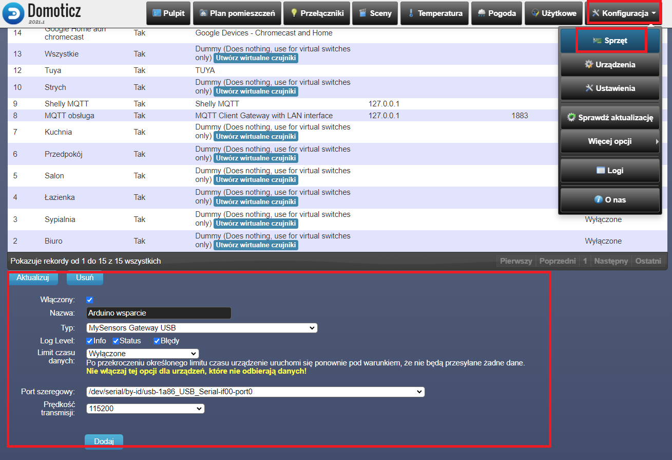
Dodajemy najpierw obsługe, czyli wchodzimy Konfiguracja >> Sprzęt i z listy na dole szukamy „MySensors Gateway USB” po wybraniu wybieramy z listy port szeregowy port do którego jest podłączone nasze arduino i dodajemy własną nazwę w polu Nazwa.
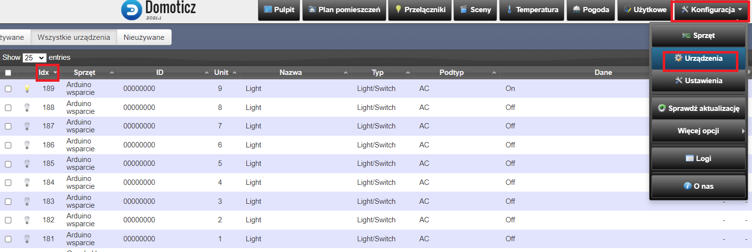
Wchodzimy Konfiguracja >> Urządzenia i segregujemy po IDX. Teraz widzimy wszystkie przekaźniki, które zostały dodane licząć od GPIO 22 do GPIO 30, czyli łącznie 9. Od tej chwili możemy włączać dane wyjścia w naszym arduino za pośrednictwem Domoticza.
Dodawanie przycisków button od zmiany statusu ON/OFF
Zacznijmy od tego, że będziemy potrzebowali nową bibliotekę
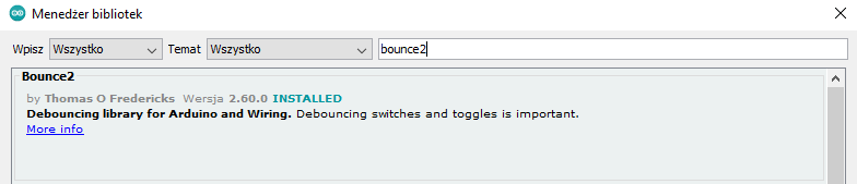
Po zainstalowaniu otwórzmy sobie przykład bounce>>more >> Change:
// This example toggles the debug LED (pin 13) on or off
// when a button on pin 2 is pressed.

// Include the Bounce2 library found here :
// https://github.com/thomasfredericks/Bounce2
#include <Bounce2.h>

#define BUTTON_PIN 2
#define LED_PIN 13

int ledState = LOW;


Bounce debouncer = Bounce(); // Instantiate a Bounce object

void setup() {

  debouncer.attach(BUTTON_PIN,INPUT_PULLUP); // Attach the debouncer to a pin with INPUT_PULLUP mode
  debouncer.interval(25); // Use a debounce interval of 25 milliseconds


  pinMode(LED_PIN,OUTPUT); // Setup the LED
  digitalWrite(LED_PIN,ledState);

}

void loop() {

   debouncer.update(); // Update the Bounce instance

   if ( debouncer.fell() ) {  // Call code if button transitions from HIGH to LOW
     ledState = !ledState; // Toggle LED state
     digitalWrite(LED_PIN,ledState); // Apply new LED state
   }
}
Po uzupełeniu naszego projektu o przycisk button:
// Enable debug prints to serial monitor
#define MY_DEBUG


// Enable and select radio type attached
//#define MY_RADIO_RF24
//#define MY_RADIO_NRF5_ESB
//#define MY_RADIO_RFM69
//#define MY_RADIO_RFM95

// Set LOW transmit power level as default, if you have an amplified NRF-module and
// power your radio separately with a good regulator you can turn up PA level.
#define MY_RF24_PA_LEVEL RF24_PA_LOW

// Enable serial gateway
#define MY_GATEWAY_SERIAL

// Define a lower baud rate for Arduinos running on 8 MHz (Arduino Pro Mini 3.3V & SenseBender)
#if F_CPU == 8000000L
#define MY_BAUD_RATE 38400
#endif

// Enable inclusion mode
//#define MY_INCLUSION_MODE_FEATURE
// Enable Inclusion mode button on gateway
//#define MY_INCLUSION_BUTTON_FEATURE

// Inverses behavior of inclusion button (if using external pullup)
//#define MY_INCLUSION_BUTTON_EXTERNAL_PULLUP

// Set inclusion mode duration (in seconds)
#define MY_INCLUSION_MODE_DURATION 60
// Digital pin used for inclusion mode button
//#define MY_INCLUSION_MODE_BUTTON_PIN  3

// Set blinking period
#define MY_DEFAULT_LED_BLINK_PERIOD 300

// Inverses the behavior of leds
//#define MY_WITH_LEDS_BLINKING_INVERSE

// Flash leds on rx/tx/err
// Uncomment to override default HW configurations
//#define MY_DEFAULT_ERR_LED_PIN 4  // Error led pin
//#define MY_DEFAULT_RX_LED_PIN  6  // Receive led pin
//#define MY_DEFAULT_TX_LED_PIN  5  // the PCB, on board LED

#include <MySensors.h>

#define RELAY_PIN 22  // Arduino Digital I/O pin number for first relay (second on pin+1 etc)
#define NUMBER_OF_RELAYS 9 // Total number of attached relays
#define RELAY_ON 1  // GPIO value to write to turn on attached relay
#define RELAY_OFF 0 // GPIO value to write to turn off attached relay
#include <Bounce2.h>

#define BUTTON_PIN 1
#define LED_PIN 30
int ledState = LOW;

Bounce debouncer = Bounce(); // Instantiate a Bounce object

MyMessage msg(1,V_LIGHT);

void before()
{
  for (int sensor=1, pin=RELAY_PIN; sensor<=NUMBER_OF_RELAYS; sensor++, pin++) {
    // Then set relay pins in output mode
    pinMode(pin, OUTPUT);
    // Set relay to last known state (using eeprom storage)
    digitalWrite(pin, loadState(sensor)?RELAY_ON:RELAY_OFF);
  }
}

void setup()
{
 debouncer.attach(BUTTON_PIN,INPUT_PULLUP); // Attach the debouncer to a pin with INPUT_PULLUP mode
  debouncer.interval(5); // Use a debounce interval of 25 milliseconds


}

void presentation()
{
  // Send the sketch version information to the gateway and Controller
  sendSketchInfo("Relay", "1.0");

  for (int sensor=1, pin=RELAY_PIN; sensor<=NUMBER_OF_RELAYS; sensor++, pin++) {
    // Register all sensors to gw (they will be created as child devices)
    present(sensor, S_LIGHT);
  }
}


void loop()
{

   debouncer.update(); // Update the Bounce instance

   if ( debouncer.fell() ) {  // Call code if button transitions from HIGH to LOW
     ledState = !ledState; // Toggle LED state
     saveState(1,ledState);
     digitalWrite(LED_PIN,ledState); // Apply new LED state
     send(msg.set(ledState));
   }
}


void receive(const MyMessage &message)
{
  // We only expect one type of message from controller. But we better check anyway.
  if (message.getType()==V_STATUS) {
    // Change relay state
    digitalWrite(message.getSensor()-1+RELAY_PIN, message.getBool()?RELAY_ON:RELAY_OFF);
    // Store state in eeprom
    saveState(message.getSensor(), message.getBool());
    // Write some debug info
    Serial.print("Incoming change for sensor:");
    Serial.print(message.getSensor());
    Serial.print(", New status: ");
    Serial.println(message.getBool());
  }
}
Powyższy kod obsługuje jeden przycisk monstabilny oraz relay w MySensors.
#define MY_DEBUG


// Enable and select radio type attached
//#define MY_RADIO_RF24
//#define MY_RADIO_NRF5_ESB
//#define MY_RADIO_RFM69
//#define MY_RADIO_RFM95

// Set LOW transmit power level as default, if you have an amplified NRF-module and
// power your radio separately with a good regulator you can turn up PA level.
#define MY_RF24_PA_LEVEL RF24_PA_LOW

// Enable serial gateway
#define MY_GATEWAY_SERIAL

// Define a lower baud rate for Arduinos running on 8 MHz (Arduino Pro Mini 3.3V & SenseBender)
#if F_CPU == 8000000L
#define MY_BAUD_RATE 38400
#endif

// Enable inclusion mode
//#define MY_INCLUSION_MODE_FEATURE
// Enable Inclusion mode button on gateway
//#define MY_INCLUSION_BUTTON_FEATURE

// Inverses behavior of inclusion button (if using external pullup)
//#define MY_INCLUSION_BUTTON_EXTERNAL_PULLUP

// Set inclusion mode duration (in seconds)
#define MY_INCLUSION_MODE_DURATION 60
// Digital pin used for inclusion mode button
//#define MY_INCLUSION_MODE_BUTTON_PIN  3

// Set blinking period
#define MY_DEFAULT_LED_BLINK_PERIOD 300

// Inverses the behavior of leds
//#define MY_WITH_LEDS_BLINKING_INVERSE

// Flash leds on rx/tx/err
// Uncomment to override default HW configurations
//#define MY_DEFAULT_ERR_LED_PIN 4  // Error led pin
//#define MY_DEFAULT_RX_LED_PIN  6  // Receive led pin
//#define MY_DEFAULT_TX_LED_PIN  5  // the PCB, on board LED

#include <SPI.h>
#include <MySensors.h>
#include <Bounce2.h>

#define RELAY_PIN0  30  // Arduino Digital I/O pin number for relay
#define RELAY_PIN1  29
#define RELAY_PIN2  28
#define RELAY_PIN3  27
#define BUTTON_PIN0  1  // Arduino Digital I/O pin number for button
#define BUTTON_PIN1  2  // Arduino Digital I/O pin number for button
#define BUTTON_PIN2  3  // Arduino Digital I/O pin number for button
#define BUTTON_PIN3  4  // Arduino Digital I/O pin number for button

#define CHILD0_ID 100   // Id of the sensor child
#define CHILD1_ID 101   // Id of the sensor child
#define CHILD2_ID 102   // Id of the sensor child
#define CHILD3_ID 103   // Id of the sensor child

#define RELAY_ON 1
#define RELAY_OFF 0

Bounce debouncerA = Bounce();
Bounce debouncerB = Bounce();
Bounce debouncerC = Bounce();
Bounce debouncerD = Bounce();

int oldValueA = 0;
int oldValueB = 0;
int oldValueC = 0;
int oldValueD = 0;

bool stateA;
bool stateB;
bool stateC;
bool stateD;

MyMessage msgA(CHILD0_ID, V_LIGHT);
MyMessage msgB(CHILD1_ID, V_LIGHT);
MyMessage msgC(CHILD2_ID, V_LIGHT);
MyMessage msgD(CHILD3_ID, V_LIGHT);

void setup()
{
  // Setup the button
  pinMode(BUTTON_PIN0, INPUT_PULLUP);
  pinMode(BUTTON_PIN1, INPUT_PULLUP);
  pinMode(BUTTON_PIN2, INPUT_PULLUP);
  pinMode(BUTTON_PIN3, INPUT_PULLUP);

  // After setting up the button, setup debouncer
  debouncerA.attach(BUTTON_PIN0);
  debouncerA.interval(5);
  debouncerB.attach(BUTTON_PIN1);
  debouncerB.interval(5);
  debouncerC.attach(BUTTON_PIN2);
  debouncerC.interval(5);
  debouncerD.attach(BUTTON_PIN3);
  debouncerD.interval(5);

  // Make sure relays are off when starting up
  digitalWrite(RELAY_PIN0, RELAY_OFF);
  digitalWrite(RELAY_PIN1, RELAY_OFF);
  digitalWrite(RELAY_PIN2, RELAY_OFF);
  digitalWrite(RELAY_PIN3, RELAY_OFF);
  // Then set relay pins in output mode
  pinMode(RELAY_PIN0, OUTPUT);
  pinMode(RELAY_PIN1, OUTPUT);
  pinMode(RELAY_PIN2, OUTPUT);
  pinMode(RELAY_PIN3, OUTPUT);


  // Set relay to last known state (using eeprom storage)
  stateA = loadState(CHILD0_ID);
  digitalWrite(RELAY_PIN0, stateA ? RELAY_ON : RELAY_OFF);

  stateB = loadState(CHILD1_ID);
  digitalWrite(RELAY_PIN1, stateB ? RELAY_ON : RELAY_OFF);

  stateC = loadState(CHILD2_ID);
  digitalWrite(RELAY_PIN2, stateC ? RELAY_ON : RELAY_OFF);

  stateD = loadState(CHILD3_ID);
  digitalWrite(RELAY_PIN3, stateD ? RELAY_ON : RELAY_OFF);
}

void presentation()  {
  // Send the sketch version information to the gateway and Controller
  sendSketchInfo("4 Relay & button", "1.0");

  // Register all sensors to gw (they will be created as child devices)
  present(CHILD0_ID, S_LIGHT);
  present(CHILD1_ID, S_LIGHT);
  present(CHILD2_ID, S_LIGHT);
  present(CHILD3_ID, S_LIGHT);
}

/*
   Example on how to asynchronously check for new messages from gw
*/
void loop()
{
  debouncerA.update();
  // Get the update value
  int valueA = debouncerA.read();
  if (valueA != oldValueA && valueA == 0) {
    send(msgA.set(stateA ? false : true), true); // Send new state and request ack back
  }
  oldValueA = valueA;

  debouncerB.update();
  // Get the update value
  int valueB = debouncerB.read();
  if (valueB != oldValueB && valueB == 0) {
    send(msgB.set(stateB ? false : true), true); // Send new state and request ack back
  }
  oldValueB = valueB;

  debouncerC.update();
  // Get the update value
  int valueC = debouncerC.read();
  if (valueC != oldValueC && valueC == 0) {
    send(msgC.set(stateC ? false : true), true); // Send new state and request ack back
  }
  oldValueC = valueC;

  debouncerD.update();
  // Get the update value
  int valueD = debouncerD.read();
  if (valueD != oldValueD && valueD == 0) {
    send(msgD.set(stateD ? false : true), true); // Send new state and request ack back
  }
  oldValueD = valueD;
}

void receive(const MyMessage &message) {
  // We only expect one type of message from controller. But we better check anyway.
  if (message.type == V_LIGHT) {

    switch (message.sensor) {
      case CHILD0_ID:
        stateA = message.getBool();
        digitalWrite(RELAY_PIN0, stateA ? RELAY_ON : RELAY_OFF);
        saveState(CHILD0_ID, stateA);
        break;

      case CHILD1_ID:
        stateB = message.getBool();
        digitalWrite(RELAY_PIN1, stateB ? RELAY_ON : RELAY_OFF);
        saveState(CHILD1_ID, stateB);
        break;

      case CHILD2_ID:
        stateC = message.getBool();
        digitalWrite(RELAY_PIN2, stateC ? RELAY_ON : RELAY_OFF);
        saveState(CHILD2_ID, stateC);
        break;

      case CHILD3_ID:
        stateD = message.getBool();
        digitalWrite(RELAY_PIN3, stateD ? RELAY_ON : RELAY_OFF);
        saveState(CHILD3_ID, stateD);
        break;
    }
    // Write some debug info
    Serial.print("Incoming change for sensor:");
    Serial.print(message.sensor);
    Serial.print(", New status: ");
    Serial.println(message.getBool());
  }
}
Powyższy kod obsługuje cztery przyciski Monostabilne oraz Relay w MySensors
#define MY_DEBUG


// Enable and select radio type attached
//#define MY_RADIO_RF24
//#define MY_RADIO_NRF5_ESB
//#define MY_RADIO_RFM69
//#define MY_RADIO_RFM95

// Set LOW transmit power level as default, if you have an amplified NRF-module and
// power your radio separately with a good regulator you can turn up PA level.
#define MY_RF24_PA_LEVEL RF24_PA_LOW

// Enable serial gateway
#define MY_GATEWAY_SERIAL

// Define a lower baud rate for Arduinos running on 8 MHz (Arduino Pro Mini 3.3V & SenseBender)
#if F_CPU == 8000000L
#define MY_BAUD_RATE 38400
#endif

// Enable inclusion mode
//#define MY_INCLUSION_MODE_FEATURE
// Enable Inclusion mode button on gateway
//#define MY_INCLUSION_BUTTON_FEATURE

// Inverses behavior of inclusion button (if using external pullup)
//#define MY_INCLUSION_BUTTON_EXTERNAL_PULLUP

// Set inclusion mode duration (in seconds)
#define MY_INCLUSION_MODE_DURATION 60
// Digital pin used for inclusion mode button
//#define MY_INCLUSION_MODE_BUTTON_PIN  3

// Set blinking period
#define MY_DEFAULT_LED_BLINK_PERIOD 300

// Inverses the behavior of leds
//#define MY_WITH_LEDS_BLINKING_INVERSE

// Flash leds on rx/tx/err
// Uncomment to override default HW configurations
//#define MY_DEFAULT_ERR_LED_PIN 4  // Error led pin
//#define MY_DEFAULT_RX_LED_PIN  6  // Receive led pin
//#define MY_DEFAULT_TX_LED_PIN  5  // the PCB, on board LED

#include <SPI.h>
#include <MySensors.h>
#include <Bounce2.h>

#define RELAY_PIN0  30  // Arduino Digital I/O pin number for relay
#define RELAY_PIN1  29
#define RELAY_PIN2  28
#define RELAY_PIN3  27
#define BUTTON_PIN0  1  // Arduino Digital I/O pin number for button
#define BUTTON_PIN1  2  // Arduino Digital I/O pin number for button
#define BUTTON_PIN2  3  // Arduino Digital I/O pin number for button
#define BUTTON_PIN3  4  // Arduino Digital I/O pin number for button

#define CHILD0_ID 100   // Id of the sensor child
#define CHILD1_ID 101   // Id of the sensor child
#define CHILD2_ID 102   // Id of the sensor child
#define CHILD3_ID 103   // Id of the sensor child

#define RELAY_ON 1
#define RELAY_OFF 0


Bounce debouncerA = Bounce();
Bounce debouncerB = Bounce();
Bounce debouncerC = Bounce();
Bounce debouncerD = Bounce();

int oldValueA = 0;
int oldValueB = 0;
int oldValueC = 0;
int oldValueD = 0;


bool stateA = false;
bool stateB = false;
bool stateC = false;
bool stateD = false;

MyMessage msgA(CHILD0_ID, V_LIGHT);
MyMessage msgB(CHILD1_ID, V_LIGHT);
MyMessage msgC(CHILD2_ID, V_LIGHT);
MyMessage msgD(CHILD3_ID, V_LIGHT);

void setup()
{
  // Setup the button
  pinMode(BUTTON_PIN0, INPUT_PULLUP);
  pinMode(BUTTON_PIN1, INPUT_PULLUP);
  pinMode(BUTTON_PIN2, INPUT_PULLUP);
  pinMode(BUTTON_PIN3, INPUT_PULLUP);

  // After setting up the button, setup debouncer
  debouncerA.attach(BUTTON_PIN0);
  debouncerA.interval(5);
  debouncerB.attach(BUTTON_PIN1);
  debouncerB.interval(5);
  debouncerC.attach(BUTTON_PIN2);
  debouncerC.interval(5);
  debouncerD.attach(BUTTON_PIN3);
  debouncerD.interval(5);

  // Make sure relays are off when starting up
  digitalWrite(RELAY_PIN0, RELAY_OFF);
  digitalWrite(RELAY_PIN1, RELAY_OFF);
  digitalWrite(RELAY_PIN2, RELAY_OFF);
  digitalWrite(RELAY_PIN3, RELAY_OFF);

  // Then set relay pins in output mode
  pinMode(RELAY_PIN0, OUTPUT);
  pinMode(RELAY_PIN1, OUTPUT);
  pinMode(RELAY_PIN2, OUTPUT);
  pinMode(RELAY_PIN3, OUTPUT);


}

void presentation()  {
  // Send the sketch version information to the gateway and Controller
  sendSketchInfo("4 Relay & button", "1.0");

  // Register all sensors to gw (they will be created as child devices)
  present(CHILD0_ID, S_LIGHT);
  present(CHILD1_ID, S_LIGHT);
  present(CHILD2_ID, S_LIGHT);
  present(CHILD3_ID, S_LIGHT);
}

/*
   Example on how to asynchronously check for new messages from gw
*/
void loop()
{
  debouncerA.update();
  // Get the update value
  int valueA = debouncerA.read();
  if (valueA != oldValueA) {
    send(msgA.set(stateA ? false : true), false); // Send new state and request ack back
    stateA = stateA ? false : true;
    digitalWrite(RELAY_PIN0, stateA ? RELAY_ON : RELAY_OFF);  // toggle the relay
      }
  oldValueA = valueA;

  debouncerB.update();
  // Get the update value
  int valueB = debouncerB.read();
  if (valueB != oldValueB) {
    send(msgB.set(stateB ? false : true), false); // Send new state and request ack back
    stateB = stateB ? false : true;
    digitalWrite(RELAY_PIN1, stateB ? RELAY_ON : RELAY_OFF);  // toggle the relay
  }
  oldValueB = valueB;

  debouncerC.update();
  // Get the update value
  int valueC = debouncerC.read();
  if (valueC != oldValueC) {
    send(msgC.set(stateC ? false : true), false); // Send new state and request ack back
    stateC = stateC ? false : true;
    digitalWrite(RELAY_PIN2, stateC ? RELAY_ON : RELAY_OFF);  // toggle the relay
  }
  oldValueC = valueC;

  debouncerD.update();
  // Get the update value
  int valueD = debouncerD.read();
  if (valueD != oldValueD) {
    send(msgD.set(stateD ? false : true), false); // Send new state and request ack back
     stateD = stateD ? false : true;
    digitalWrite(RELAY_PIN3, stateD ? RELAY_ON : RELAY_OFF);  // toggle the relay
  }
  oldValueD = valueD;
}

void receive(const MyMessage &message) {
  // We only expect one type of message from controller. But we better check anyway.
  if (message.type == V_LIGHT) {

    switch (message.sensor) {
      case CHILD0_ID:
        stateA = message.getBool();
        digitalWrite(RELAY_PIN0, stateA ? RELAY_ON : RELAY_OFF);
        saveState(CHILD0_ID, stateA);
        break;

      case CHILD1_ID:
        stateB = message.getBool();
        digitalWrite(RELAY_PIN1, stateB ? RELAY_ON : RELAY_OFF);
        saveState(CHILD1_ID, stateB);
        break;

      case CHILD2_ID:
        stateC = message.getBool();
        digitalWrite(RELAY_PIN2, stateC ? RELAY_ON : RELAY_OFF);
        saveState(CHILD2_ID, stateC);
        break;

      case CHILD3_ID:
        stateD = message.getBool();
        digitalWrite(RELAY_PIN3, stateD ? RELAY_ON : RELAY_OFF);
        saveState(CHILD3_ID, stateD);
        break;
    }
    // Write some debug info
    Serial.print("Incoming change for sensor:");
    Serial.print(message.sensor);
    Serial.print(", New status: ");
    Serial.println(message.getBool());
  }
}
Powyższy kod obsługuje cztery przyciski Bistabilne oraz Relay w MySensors
#define MY_DEBUG

// Enable and select radio type attached
//#define MY_RADIO_RF24
//#define MY_RADIO_NRF5_ESB
//#define MY_RADIO_RFM69
//#define MY_RADIO_RFM95

// Set LOW transmit power level as default, if you have an amplified NRF-module and
// power your radio separately with a good regulator you can turn up PA level.
#define MY_RF24_PA_LEVEL RF24_PA_LOW

// Enable serial gateway
#define MY_GATEWAY_SERIAL

// Define a lower baud rate for Arduinos running on 8 MHz (Arduino Pro Mini 3.3V & SenseBender)
#if F_CPU == 8000000L
#define MY_BAUD_RATE 38400
#endif

// Enable inclusion mode
//#define MY_INCLUSION_MODE_FEATURE
// Enable Inclusion mode button on gateway
//#define MY_INCLUSION_BUTTON_FEATURE

// Inverses behavior of inclusion button (if using external pullup)
//#define MY_INCLUSION_BUTTON_EXTERNAL_PULLUP

// Set inclusion mode duration (in seconds)
#define MY_INCLUSION_MODE_DURATION 60
// Digital pin used for inclusion mode button
//#define MY_INCLUSION_MODE_BUTTON_PIN  3

// Set blinking period
#define MY_DEFAULT_LED_BLINK_PERIOD 300

// Inverses the behavior of leds
//#define MY_WITH_LEDS_BLINKING_INVERSE

// Flash leds on rx/tx/err
// Uncomment to override default HW configurations
//#define MY_DEFAULT_ERR_LED_PIN 4  // Error led pin
//#define MY_DEFAULT_RX_LED_PIN  6  // Receive led pin
//#define MY_DEFAULT_TX_LED_PIN  5  // the PCB, on board LED

#include <SPI.h>
#include <MySensors.h>
#include <Bounce2.h>

#define RELAY_PIN0  22  // Arduino Digital I/O pin number for relay
#define RELAY_PIN1  23
#define RELAY_PIN2  24
#define RELAY_PIN3  25
#define RELAY_PIN4  26  // Arduino Digital I/O pin number for relay
#define RELAY_PIN5  27
#define RELAY_PIN6  28
#define RELAY_PIN7  29
#define RELAY_PIN8  30  // Arduino Digital I/O pin number for relay
#define RELAY_PIN9  31
#define RELAY_PIN10  32
#define RELAY_PIN11  33
#define RELAY_PIN12  34  // Arduino Digital I/O pin number for relay
#define RELAY_PIN13  35
#define RELAY_PIN14  36
#define RELAY_PIN15  37
#define RELAY_PIN16  38
#define RELAY_PIN17  39  // Arduino Digital I/O pin number for relay
#define RELAY_PIN18  40
#define RELAY_PIN19  41
#define RELAY_PIN20  42

#define BUTTON_PIN0  A0  // Arduino Digital I/O pin number for button
#define BUTTON_PIN1  A1  // Arduino Digital I/O pin number for button
#define BUTTON_PIN2  A2  // Arduino Digital I/O pin number for button
#define BUTTON_PIN3  A3  // Arduino Digital I/O pin number for button
#define BUTTON_PIN4  A4  // Arduino Digital I/O pin number for button
#define BUTTON_PIN5  A5  // Arduino Digital I/O pin number for button
#define BUTTON_PIN6  A6  // Arduino Digital I/O pin number for button
#define BUTTON_PIN7  A7  // Arduino Digital I/O pin number for button
#define BUTTON_PIN8  A8  // Arduino Digital I/O pin number for button
#define BUTTON_PIN9  A9  // Arduino Digital I/O pin number for button
#define BUTTON_PIN10  A10 // Arduino Digital I/O pin number for button
#define BUTTON_PIN11  A11 // Arduino Digital I/O pin number for button
#define BUTTON_PIN12  A12 // Arduino Digital I/O pin number for button
#define BUTTON_PIN13  A13 // Arduino Digital I/O pin number for button
#define BUTTON_PIN14  A14 // Arduino Digital I/O pin number for button
#define BUTTON_PIN15  53 // Arduino Digital I/O pin number for button
#define BUTTON_PIN16  52 // Arduino Digital I/O pin number for button
#define BUTTON_PIN17  51 // Arduino Digital I/O pin number for button
#define BUTTON_PIN18  50 // Arduino Digital I/O pin number for button
#define BUTTON_PIN19  49 // Arduino Digital I/O pin number for button
#define BUTTON_PIN20  48 // Arduino Digital I/O pin number for button


#define CHILD0_ID 100   // Id of the sensor child
#define CHILD1_ID 101   // Id of the sensor child
#define CHILD2_ID 102   // Id of the sensor child
#define CHILD3_ID 103   // Id of the sensor child
#define CHILD4_ID 104   // Id of the sensor child
#define CHILD5_ID 105   // Id of the sensor child
#define CHILD6_ID 106   // Id of the sensor child
#define CHILD7_ID 107   // Id of the sensor child
#define CHILD8_ID 108   // Id of the sensor child
#define CHILD9_ID 109   // Id of the sensor child
#define CHILD10_ID 110   // Id of the sensor child
#define CHILD11_ID 111   // Id of the sensor child
#define CHILD12_ID 112   // Id of the sensor child
#define CHILD13_ID 113   // Id of the sensor child
#define CHILD14_ID 114   // Id of the sensor child
#define CHILD15_ID 115   // Id of the sensor child
#define CHILD16_ID 116   // Id of the sensor child
#define CHILD17_ID 117   // Id of the sensor child
#define CHILD18_ID 118   // Id of the sensor child
#define CHILD19_ID 119   // Id of the sensor child
#define CHILD20_ID 120   // Id of the sensor child


#define RELAY_ON 1
#define RELAY_OFF 0

//A B C D E F G H I J K L M N O P R S T W X

Bounce debouncerA = Bounce(); //1
Bounce debouncerB = Bounce();
Bounce debouncerC = Bounce();
Bounce debouncerD = Bounce();
Bounce debouncerE = Bounce(); //5
Bounce debouncerF = Bounce();
Bounce debouncerG = Bounce();
Bounce debouncerH = Bounce();
Bounce debouncerI = Bounce();
Bounce debouncerJ = Bounce(); //10
Bounce debouncerK = Bounce();
Bounce debouncerL = Bounce();
Bounce debouncerM = Bounce();
Bounce debouncerN = Bounce();
Bounce debouncerO = Bounce(); //15
Bounce debouncerP = Bounce();
Bounce debouncerR = Bounce();
Bounce debouncerS = Bounce();
Bounce debouncerT = Bounce();
Bounce debouncerW = Bounce(); //20
Bounce debouncerX = Bounce();

//A B C D E F G H I J K L M N O P R S T W X
int oldValueA = 0; //1
int oldValueB = 0;
int oldValueC = 0;
int oldValueD = 0;
int oldValueE = 0; //5
int oldValueF = 0;
int oldValueG = 0;
int oldValueH = 0;
int oldValueI = 0;
int oldValueJ = 0; //10
int oldValueK = 0;
int oldValueL = 0;
int oldValueM = 0;
int oldValueN = 0;
int oldValueO = 0; //15
int oldValueP = 0;
int oldValueR = 0;
int oldValueS = 0;
int oldValueT = 0;
int oldValueW = 0; //20
int oldValueX = 0;

//A B C D E F G H I J K L M N O P R S T W X
bool stateA = false; //1
bool stateB = false;
bool stateC = false;
bool stateD = false;
bool stateE = false; //5
bool stateF = false;
bool stateG = false;
bool stateH = false;
bool stateI = false;
bool stateJ = false; //10
bool stateK = false;
bool stateL = false;
bool stateM = false;
bool stateN = false;
bool stateO = false; //15
bool stateP = false;
bool stateR = false;
bool stateS = false;
bool stateT = false;
bool stateW = false; //20
bool stateX = false;

//A B C D E F G H I J K L M N O P R S T W X
MyMessage msgA(CHILD0_ID, V_LIGHT); //1
MyMessage msgB(CHILD1_ID, V_LIGHT);
MyMessage msgC(CHILD2_ID, V_LIGHT);
MyMessage msgD(CHILD3_ID, V_LIGHT);
MyMessage msgE(CHILD4_ID, V_LIGHT); //5
MyMessage msgF(CHILD5_ID, V_LIGHT);
MyMessage msgG(CHILD6_ID, V_LIGHT);
MyMessage msgH(CHILD7_ID, V_LIGHT);
MyMessage msgI(CHILD8_ID, V_LIGHT);
MyMessage msgJ(CHILD9_ID, V_LIGHT); //10
MyMessage msgK(CHILD10_ID, V_LIGHT);
MyMessage msgL(CHILD11_ID, V_LIGHT);
MyMessage msgM(CHILD12_ID, V_LIGHT);
MyMessage msgN(CHILD13_ID, V_LIGHT);
MyMessage msgO(CHILD14_ID, V_LIGHT); //15
MyMessage msgP(CHILD15_ID, V_LIGHT);
MyMessage msgR(CHILD16_ID, V_LIGHT);
MyMessage msgS(CHILD17_ID, V_LIGHT);
MyMessage msgT(CHILD18_ID, V_LIGHT);
MyMessage msgW(CHILD19_ID, V_LIGHT); //20
MyMessage msgX(CHILD20_ID, V_LIGHT);

void setup()
{
  // Setup the button
  pinMode(BUTTON_PIN0, INPUT_PULLUP); //1
  pinMode(BUTTON_PIN1, INPUT_PULLUP);
  pinMode(BUTTON_PIN2, INPUT_PULLUP);
  pinMode(BUTTON_PIN3, INPUT_PULLUP);
  pinMode(BUTTON_PIN4, INPUT_PULLUP); //5
  pinMode(BUTTON_PIN5, INPUT_PULLUP);
  pinMode(BUTTON_PIN6, INPUT_PULLUP);
  pinMode(BUTTON_PIN7, INPUT_PULLUP);
  pinMode(BUTTON_PIN8, INPUT_PULLUP);
  pinMode(BUTTON_PIN9, INPUT_PULLUP); //10
  pinMode(BUTTON_PIN10, INPUT_PULLUP);
  pinMode(BUTTON_PIN11, INPUT_PULLUP);
  pinMode(BUTTON_PIN12, INPUT_PULLUP);
  pinMode(BUTTON_PIN13, INPUT_PULLUP);
  pinMode(BUTTON_PIN14, INPUT_PULLUP); //15
  pinMode(BUTTON_PIN15, INPUT_PULLUP);
  pinMode(BUTTON_PIN16, INPUT_PULLUP);
  pinMode(BUTTON_PIN17, INPUT_PULLUP);
  pinMode(BUTTON_PIN18, INPUT_PULLUP);
  pinMode(BUTTON_PIN19, INPUT_PULLUP); //20
  pinMode(BUTTON_PIN20, INPUT_PULLUP);


  // After setting up the button, setup debouncer
  debouncerA.attach(BUTTON_PIN0); //1
  debouncerA.interval(5);
  debouncerB.attach(BUTTON_PIN1);
  debouncerB.interval(5);
  debouncerC.attach(BUTTON_PIN2);
  debouncerC.interval(5);
  debouncerD.attach(BUTTON_PIN3);
  debouncerD.interval(5);
  debouncerE.attach(BUTTON_PIN4); //5
  debouncerE.interval(5);
  debouncerF.attach(BUTTON_PIN5);
  debouncerF.interval(5);
  debouncerG.attach(BUTTON_PIN6);
  debouncerG.interval(5);
  debouncerH.attach(BUTTON_PIN7);
  debouncerH.interval(5);
  debouncerI.attach(BUTTON_PIN8);
  debouncerI.interval(5);
  debouncerJ.attach(BUTTON_PIN9); //10
  debouncerJ.interval(5);
  debouncerK.attach(BUTTON_PIN10);
  debouncerK.interval(5);
  debouncerL.attach(BUTTON_PIN11);
  debouncerL.interval(5);
  debouncerM.attach(BUTTON_PIN12);
  debouncerM.interval(5);
  debouncerN.attach(BUTTON_PIN13);
  debouncerN.interval(5);
  debouncerO.attach(BUTTON_PIN14); //15
  debouncerO.interval(5);
  debouncerP.attach(BUTTON_PIN15);
  debouncerP.interval(5);
  debouncerR.attach(BUTTON_PIN16);
  debouncerR.interval(5);
  debouncerS.attach(BUTTON_PIN17);
  debouncerS.interval(5);
  debouncerT.attach(BUTTON_PIN18);
  debouncerT.interval(5);
  debouncerW.attach(BUTTON_PIN19); //20
  debouncerW.interval(5);
  debouncerX.attach(BUTTON_PIN20);
  debouncerX.interval(5);

  // Make sure relays are off when starting up
  digitalWrite(RELAY_PIN0, RELAY_OFF); //1
  digitalWrite(RELAY_PIN1, RELAY_OFF);
  digitalWrite(RELAY_PIN2, RELAY_OFF);
  digitalWrite(RELAY_PIN3, RELAY_OFF);
  digitalWrite(RELAY_PIN4, RELAY_OFF); //5
  digitalWrite(RELAY_PIN5, RELAY_OFF);
  digitalWrite(RELAY_PIN6, RELAY_OFF);
  digitalWrite(RELAY_PIN7, RELAY_OFF);
  digitalWrite(RELAY_PIN8, RELAY_OFF);
  digitalWrite(RELAY_PIN9, RELAY_OFF); //10
  digitalWrite(RELAY_PIN10, RELAY_OFF);
  digitalWrite(RELAY_PIN11, RELAY_OFF);
  digitalWrite(RELAY_PIN12, RELAY_OFF);
  digitalWrite(RELAY_PIN13, RELAY_OFF);
  digitalWrite(RELAY_PIN14, RELAY_OFF); //15
  digitalWrite(RELAY_PIN15, RELAY_OFF);
  digitalWrite(RELAY_PIN16, RELAY_OFF);
  digitalWrite(RELAY_PIN17, RELAY_OFF);
  digitalWrite(RELAY_PIN18, RELAY_OFF);
  digitalWrite(RELAY_PIN19, RELAY_OFF); //20
  digitalWrite(RELAY_PIN20, RELAY_OFF);

  // Then set relay pins in output mode
  pinMode(RELAY_PIN0, OUTPUT); //1
  pinMode(RELAY_PIN1, OUTPUT);
  pinMode(RELAY_PIN2, OUTPUT);
  pinMode(RELAY_PIN3, OUTPUT);
  pinMode(RELAY_PIN4, OUTPUT); //5
  pinMode(RELAY_PIN5, OUTPUT);
  pinMode(RELAY_PIN6, OUTPUT);
  pinMode(RELAY_PIN7, OUTPUT);
  pinMode(RELAY_PIN8, OUTPUT);
  pinMode(RELAY_PIN9, OUTPUT); //10
  pinMode(RELAY_PIN10, OUTPUT);
  pinMode(RELAY_PIN11, OUTPUT);
  pinMode(RELAY_PIN12, OUTPUT);
  pinMode(RELAY_PIN13, OUTPUT);
  pinMode(RELAY_PIN14, OUTPUT); //15
  pinMode(RELAY_PIN15, OUTPUT);
  pinMode(RELAY_PIN16, OUTPUT);
  pinMode(RELAY_PIN17, OUTPUT);
  pinMode(RELAY_PIN18, OUTPUT);
  pinMode(RELAY_PIN19, OUTPUT); //20
  pinMode(RELAY_PIN20, OUTPUT);


}

void presentation()  {
  // Send the sketch version information to the gateway and Controller
  sendSketchInfo("21 Relay & button", "2.0");

  // Register all sensors to gw (they will be created as child devices)
  present(CHILD0_ID, S_LIGHT);
  present(CHILD1_ID, S_LIGHT);
  present(CHILD2_ID, S_LIGHT);
  present(CHILD3_ID, S_LIGHT);
  present(CHILD4_ID, S_LIGHT); //5
  present(CHILD5_ID, S_LIGHT);
  present(CHILD6_ID, S_LIGHT);
  present(CHILD7_ID, S_LIGHT);
  present(CHILD8_ID, S_LIGHT);
  present(CHILD9_ID, S_LIGHT); //10
  present(CHILD10_ID, S_LIGHT);
  present(CHILD11_ID, S_LIGHT);
  present(CHILD12_ID, S_LIGHT);
  present(CHILD13_ID, S_LIGHT);
  present(CHILD14_ID, S_LIGHT); //15
  present(CHILD15_ID, S_LIGHT);
  present(CHILD16_ID, S_LIGHT);
  present(CHILD17_ID, S_LIGHT);
  present(CHILD18_ID, S_LIGHT);
  present(CHILD19_ID, S_LIGHT); //20
  present(CHILD20_ID, S_LIGHT);
}

/*
   Example on how to asynchronously check for new messages from gw
*/
void loop()
{
  debouncerA.update();
  // Get the update value
  int valueA = debouncerA.read();
  if (valueA != oldValueA) {
    send(msgA.set(stateA ? false : true), false); // Send new state and request ack back
    stateA = stateA ? false : true;
    digitalWrite(RELAY_PIN0, stateA ? RELAY_ON : RELAY_OFF);  // toggle the relay
      }
  oldValueA = valueA;

  debouncerB.update();
  // Get the update value
  int valueB = debouncerB.read();
  if (valueB != oldValueB) {
    send(msgB.set(stateB ? false : true), false); // Send new state and request ack back
    stateB = stateB ? false : true;
    digitalWrite(RELAY_PIN1, stateB ? RELAY_ON : RELAY_OFF);  // toggle the relay
  }
  oldValueB = valueB;

  debouncerC.update();
  // Get the update value
  int valueC = debouncerC.read();
  if (valueC != oldValueC) {
    send(msgC.set(stateC ? false : true), false); // Send new state and request ack back
    stateC = stateC ? false : true;
    digitalWrite(RELAY_PIN2, stateC ? RELAY_ON : RELAY_OFF);  // toggle the relay
  }
  oldValueC = valueC;

  debouncerD.update();
  // Get the update value
  int valueD = debouncerD.read();
  if (valueD != oldValueD) {
    send(msgD.set(stateD ? false : true), false); // Send new state and request ack back
     stateD = stateD ? false : true;
    digitalWrite(RELAY_PIN3, stateD ? RELAY_ON : RELAY_OFF);  // toggle the relay
  }
  oldValueD = valueD;

  debouncerE.update();
  // Get the update value
  int valueE = debouncerE.read();
  if (valueE != oldValueE) {
    send(msgE.set(stateE ? false : true), false); // Send new state and request ack back
     stateE = stateE ? false : true;
    digitalWrite(RELAY_PIN4, stateE ? RELAY_ON : RELAY_OFF);  // toggle the relay
  }
  oldValueE = valueE; //5

    debouncerF.update();
  // Get the update value
  int valueF = debouncerF.read();
  if (valueF != oldValueF) {
    send(msgF.set(stateF ? false : true), false); // Send new state and request ack back
    stateF = stateF ? false : true;
    digitalWrite(RELAY_PIN5, stateF ? RELAY_ON : RELAY_OFF);  // toggle the relay
      }
  oldValueF = valueF;

  debouncerG.update();
  // Get the update value
  int valueG = debouncerG.read();
  if (valueG != oldValueG) {
    send(msgG.set(stateG ? false : true), false); // Send new state and request ack back
    stateG = stateG ? false : true;
    digitalWrite(RELAY_PIN6, stateG ? RELAY_ON : RELAY_OFF);  // toggle the relay
  }
  oldValueG = valueG;

  debouncerH.update();
  // Get the update value
  int valueH = debouncerH.read();
  if (valueH != oldValueH) {
    send(msgH.set(stateH ? false : true), false); // Send new state and request ack back
    stateH = stateH ? false : true;
    digitalWrite(RELAY_PIN7, stateH ? RELAY_ON : RELAY_OFF);  // toggle the relay
  }
  oldValueH = valueH;

  debouncerI.update();
  // Get the update value
  int valueI = debouncerI.read();
  if (valueI != oldValueI) {
    send(msgI.set(stateI ? false : true), false); // Send new state and request ack back
     stateI = stateI ? false : true;
    digitalWrite(RELAY_PIN8, stateI ? RELAY_ON : RELAY_OFF);  // toggle the relay
  }
  oldValueI = valueI;

  debouncerJ.update();
  // Get the update value
  int valueJ = debouncerJ.read();
  if (valueJ != oldValueJ) {
    send(msgJ.set(stateJ ? false : true), false); // Send new state and request ack back
     stateJ = stateJ ? false : true;
    digitalWrite(RELAY_PIN9, stateJ ? RELAY_ON : RELAY_OFF);  // toggle the relay
  }
  oldValueJ = valueJ; //10

    debouncerK.update();
  // Get the update value
  int valueK = debouncerK.read();
  if (valueK != oldValueK) {
    send(msgK.set(stateK ? false : true), false); // Send new state and request ack back
    stateK = stateK ? false : true;
    digitalWrite(RELAY_PIN10, stateK ? RELAY_ON : RELAY_OFF);  // toggle the relay
      }
  oldValueK = valueK;

  debouncerL.update();
  // Get the update value
  int valueL = debouncerL.read();
  if (valueL != oldValueL) {
    send(msgL.set(stateL ? false : true), false); // Send new state and request ack back
    stateL = stateL ? false : true;
    digitalWrite(RELAY_PIN11, stateL ? RELAY_ON : RELAY_OFF);  // toggle the relay
  }
  oldValueL = valueL;

  debouncerM.update();
  // Get the update value
  int valueM = debouncerM.read();
  if (valueM != oldValueM) {
    send(msgM.set(stateM ? false : true), false); // Send new state and request ack back
    stateM = stateM ? false : true;
    digitalWrite(RELAY_PIN12, stateM ? RELAY_ON : RELAY_OFF);  // toggle the relay
  }
  oldValueM = valueM;

  debouncerN.update();
  // Get the update value
  int valueN = debouncerN.read();
  if (valueN != oldValueN) {
    send(msgN.set(stateN ? false : true), false); // Send new state and request ack back
     stateN = stateN ? false : true;
    digitalWrite(RELAY_PIN13, stateN ? RELAY_ON : RELAY_OFF);  // toggle the relay
  }
  oldValueN = valueN;

  debouncerO.update();
  // Get the update value
  int valueO = debouncerO.read();
  if (valueO != oldValueO) {
    send(msgO.set(stateO ? false : true), false); // Send new state and request ack back
     stateO = stateO ? false : true;
    digitalWrite(RELAY_PIN14, stateO ? RELAY_ON : RELAY_OFF);  // toggle the relay
  }
  oldValueO = valueO; //15

    debouncerP.update();
  // Get the update value
  int valueP = debouncerP.read();
  if (valueP != oldValueP) {
    send(msgP.set(stateP ? false : true), false); // Send new state and request ack back
    stateP = stateP ? false : true;
    digitalWrite(RELAY_PIN15, stateP ? RELAY_ON : RELAY_OFF);  // toggle the relay
      }
  oldValueP = valueP;

  debouncerR.update();
  // Get the update value
  int valueR = debouncerR.read();
  if (valueR != oldValueR) {
    send(msgR.set(stateR ? false : true), false); // Send new state and request ack back
    stateR = stateR ? false : true;
    digitalWrite(RELAY_PIN16, stateR ? RELAY_ON : RELAY_OFF);  // toggle the relay
  }
  oldValueR = valueR;

  debouncerS.update();
  // Get the update value
  int valueS = debouncerS.read();
  if (valueS != oldValueS) {
    send(msgS.set(stateS ? false : true), false); // Send new state and request ack back
    stateS = stateS ? false : true;
    digitalWrite(RELAY_PIN17, stateS ? RELAY_ON : RELAY_OFF);  // toggle the relay
  }
  oldValueS = valueS;

  debouncerT.update();
  // Get the update value
  int valueT = debouncerT.read();
  if (valueT != oldValueT) {
    send(msgT.set(stateT ? false : true), false); // Send new state and request ack back
     stateT = stateT ? false : true;
    digitalWrite(RELAY_PIN18, stateT ? RELAY_ON : RELAY_OFF);  // toggle the relay
  }
  oldValueT = valueT;

  debouncerW.update();
  // Get the update value
  int valueW = debouncerW.read();
  if (valueW != oldValueW) {
    send(msgW.set(stateW ? false : true), false); // Send new state and request ack back
     stateW = stateW ? false : true;
    digitalWrite(RELAY_PIN19, stateW ? RELAY_ON : RELAY_OFF);  // toggle the relay
  }
  oldValueW = valueW; //20

    debouncerX.update();
  // Get the update value
  int valueX = debouncerX.read();
  if (valueX != oldValueX) {
    send(msgX.set(stateX ? false : true), false); // Send new state and request ack back
     stateX = stateX ? false : true;
    digitalWrite(RELAY_PIN20, stateX ? RELAY_ON : RELAY_OFF);  // toggle the relay
  }
  oldValueX = valueX;
}

void receive(const MyMessage &message) {
  // We only expect one type of message from controller. But we better check anyway.
  if (message.type == V_LIGHT) {

    switch (message.sensor) {
      case CHILD0_ID:
        stateA = message.getBool();
        digitalWrite(RELAY_PIN0, stateA ? RELAY_ON : RELAY_OFF);
        saveState(CHILD0_ID, stateA);
        break;

      case CHILD1_ID:
        stateB = message.getBool();
        digitalWrite(RELAY_PIN1, stateB ? RELAY_ON : RELAY_OFF);
        saveState(CHILD1_ID, stateB);
        break;

      case CHILD2_ID:
        stateC = message.getBool();
        digitalWrite(RELAY_PIN2, stateC ? RELAY_ON : RELAY_OFF);
        saveState(CHILD2_ID, stateC);
        break;

      case CHILD3_ID:
        stateD = message.getBool();
        digitalWrite(RELAY_PIN3, stateD ? RELAY_ON : RELAY_OFF);
        saveState(CHILD3_ID, stateD);
        break;

      case CHILD4_ID:
        stateE = message.getBool();
        digitalWrite(RELAY_PIN4, stateE ? RELAY_ON : RELAY_OFF);
        saveState(CHILD4_ID, stateE);
        break;  //5

      case CHILD5_ID:
        stateF = message.getBool();
        digitalWrite(RELAY_PIN5, stateF ? RELAY_ON : RELAY_OFF);
        saveState(CHILD5_ID, stateF);
        break;

      case CHILD6_ID:
        stateG = message.getBool();
        digitalWrite(RELAY_PIN6, stateG ? RELAY_ON : RELAY_OFF);
        saveState(CHILD6_ID, stateG);
        break;

      case CHILD7_ID:
        stateH = message.getBool();
        digitalWrite(RELAY_PIN7, stateH ? RELAY_ON : RELAY_OFF);
        saveState(CHILD7_ID, stateH);
        break;

      case CHILD8_ID:
        stateI = message.getBool();
        digitalWrite(RELAY_PIN8, stateI ? RELAY_ON : RELAY_OFF);
        saveState(CHILD8_ID, stateI);
        break;

      case CHILD9_ID:
        stateJ = message.getBool();
        digitalWrite(RELAY_PIN9, stateJ ? RELAY_ON : RELAY_OFF);
        saveState(CHILD9_ID, stateJ);
        break;  //10

      case CHILD10_ID:
        stateK = message.getBool();
        digitalWrite(RELAY_PIN10, stateK ? RELAY_ON : RELAY_OFF);
        saveState(CHILD10_ID, stateK);
        break;

      case CHILD11_ID:
        stateL = message.getBool();
        digitalWrite(RELAY_PIN11, stateL ? RELAY_ON : RELAY_OFF);
        saveState(CHILD11_ID, stateL);
        break;

      case CHILD12_ID:
        stateM = message.getBool();
        digitalWrite(RELAY_PIN12, stateM ? RELAY_ON : RELAY_OFF);
        saveState(CHILD12_ID, stateM);
        break;

      case CHILD13_ID:
        stateN = message.getBool();
        digitalWrite(RELAY_PIN13, stateN ? RELAY_ON : RELAY_OFF);
        saveState(CHILD13_ID, stateN);
        break;

      case CHILD14_ID:
        stateO = message.getBool();
        digitalWrite(RELAY_PIN14, stateO ? RELAY_ON : RELAY_OFF);
        saveState(CHILD14_ID, stateO);
        break;  //15

      case CHILD15_ID:
        stateP = message.getBool();
        digitalWrite(RELAY_PIN15, stateP ? RELAY_ON : RELAY_OFF);
        saveState(CHILD15_ID, stateP);
        break;

      case CHILD16_ID:
        stateR = message.getBool();
        digitalWrite(RELAY_PIN16, stateR ? RELAY_ON : RELAY_OFF);
        saveState(CHILD16_ID, stateR);
        break;

      case CHILD17_ID:
        stateS = message.getBool();
        digitalWrite(RELAY_PIN17, stateS ? RELAY_ON : RELAY_OFF);
        saveState(CHILD17_ID, stateS);
        break;

      case CHILD18_ID:
        stateT = message.getBool();
        digitalWrite(RELAY_PIN18, stateT ? RELAY_ON : RELAY_OFF);
        saveState(CHILD18_ID, stateT);
        break;

      case CHILD19_ID:
        stateW = message.getBool();
        digitalWrite(RELAY_PIN19, stateW ? RELAY_ON : RELAY_OFF);
        saveState(CHILD19_ID, stateW);
        break;  //20

      case CHILD20_ID:
        stateX = message.getBool();
        digitalWrite(RELAY_PIN20, stateX ? RELAY_ON : RELAY_OFF);
        saveState(CHILD20_ID, stateX);
        break;
    }
    // Write some debug info
    Serial.print("Incoming change for sensor:");
    Serial.print(message.sensor);
    Serial.print(", New status: ");
    Serial.println(message.getBool());
  }
}
Powyższy kod obsługuje 21 sterowników Bistabilnych oraz przełączników.